
7 CCS Busbar Buying Tips for Global Buyers

A CCS Busbar can look simple in a drawing, yet small design choices affect fit, heat, and assembly. For global buyers, comparing quotations on price alone can hide important differences. Current rating, conductor material, plating, insulation, and connection geometry all need to match the actual application. A few millimeters can matter when the busbar must fit inside a battery pack or power cabinet. Small details matter.

This guide outlines seven practical checks before placing an order. It covers how to clarify electrical and mechanical requirements, assess manufacturing capability, review samples, and ask for useful quality records. Buyers should also confirm how suppliers control dimensions, surface finish, insulation, and production changes. These checks help teams compare offers on more than unit cost. They can also expose gaps before tooling or volume production begins.

There is no single specification that suits every project. A design for a compact energy storage system may face different space, temperature, and vibration demands from one used in industrial equipment. Share drawings and operating conditions with qualified engineers, then verify proposed ratings and test methods against the application. Do not assume a supplier’s standard design is automatically suitable. That takes patience. Even a thorough review can miss something, so document open questions and resolve them before approval. The following buying tips provide a clear starting point for selecting a CCS Busbar and building a more reliable supplier relationship.
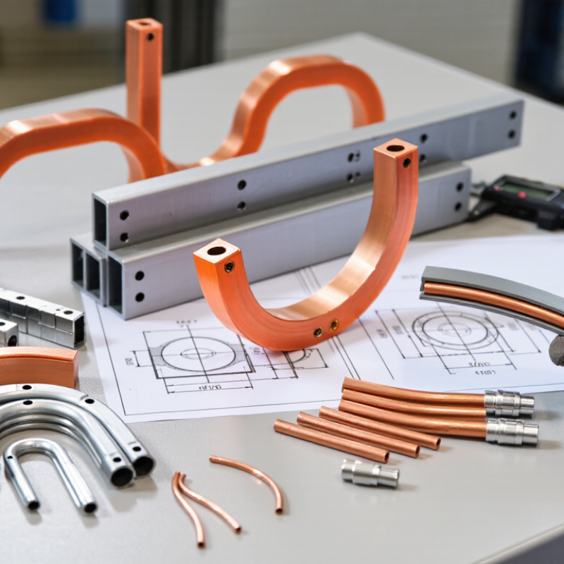
7 CCS Busbar Buying Tips for Global Buyers

Define Copper-Clad Steel (CCS) Busbar Duty and Operating Conditions

Before selecting a copper-clad steel (CCS) busbar, define the work it must perform. Record continuous current, peak load, voltage, and any short-duration overloads. Measure, don’t guess. A busbar carrying steady current in a warm, enclosed cabinet faces different conditions from one installed in open air. Note ambient temperature, ventilation, enclosure material, and nearby heat sources. These details affect temperature rise and practical current capacity. CCS combines a steel core with a copper layer, so its electrical and thermal behavior differs from solid copper. Use supplier data for the specific dimensions and construction; avoid applying copper-busbar assumptions without checking.

Also describe the electrical duty at the connection points. Document AC or DC operation, system frequency, expected fault current, and permitted voltage drop. For AC systems, frequency and bar thickness can influence current distribution. Check joint design, too: contact area, fastener arrangement, and surface preparation all affect heating. Small details matter. In practice, early load estimates can be optimistic, especially where equipment cycles or future expansion is likely. Leave room to review those assumptions against measured loads and the actual installation. Define the operating limits before comparing quotations, so each proposal addresses the same conditions.

7 CCS Busbar Buying Tips for Global Buyers - Define Copper-Clad Steel (CCS) Busbar Duty and Operating Conditions

No. Buying Tip What to Define Practical Specification Details Why It Matters
1 Define the electrical duty State the system voltage, continuous current, load profile, and whether the busbar carries AC or DC. For example: 800 A continuous DC duty, or a stated AC current at the system frequency. Identify expected overloads, load cycles, and fault-current requirements separately. Current capacity depends on conductor dimensions, installation, cooling, connections, and allowable temperature rise; a current rating alone is not a complete specification.
2 Describe operating and ambient conditions Provide ambient temperature range, altitude, humidity, ventilation, enclosure type, and exposure to dust, salt, or chemicals. Specify the intended indoor or outdoor location, whether the bar is enclosed or open-air, and any condensation or corrosive-atmosphere risks. Heat dissipation and corrosion exposure affect material selection, surface protection, clearances, and the appropriate design temperature limits.
3 Specify the CCS construction Define the steel core, copper cladding, manufacturing route, and required cladding thickness or copper-to-steel ratio. Request a cross-section drawing and a stated method for measuring cladding thickness and verifying the copper-to-steel bond. Confirm whether the cladding is continuous over all required surfaces. CCS combines a conductive copper exterior with a steel core, but its electrical and mechanical performance depends on the actual geometry and quality of the composite bond.
4 Match size to electrical and mechanical needs Set width, thickness, length, tolerances, hole pattern, bend geometry, and allowable deflection or support spacing. Provide dimensioned drawings, edge and corner requirements, hole sizes, and the number and location of bends. State whether the busbar must fit existing equipment. Steel can provide greater stiffness than copper of comparable geometry, but the finished assembly still needs verification for current capacity, short-circuit forces, and fit.
5 Plan joints and contact surfaces Identify connection materials, mating surfaces, fasteners, contact pressure, and any plating or surface-finish requirements. Specify connection-hole tolerances, required contact area, joining method, and assembly torque by reference to the equipment or joint design. Confirm that copper cladding is present at contact areas. Joint resistance can create localized heating. Reliable contact depends on compatible surfaces, adequate pressure, clean assembly, and controlled installation.
6 Set fault and safety requirements Provide prospective short-circuit current, fault duration, protective-device clearing time, and required clearances or insulation details. State the applicable system design basis and request evidence that the complete busbar arrangement and supports are suitable for the specified fault duty. Short-circuit forces and thermal stress affect the busbar, supports, joints, and enclosure. A material description by itself does not establish assembly safety.
7 Agree on verification and documentation Define inspection points, test methods, acceptance criteria, traceability, packaging, and destination-market requirements. Request dimensional inspection results, material and cladding documentation, electrical test data where applicable, drawings, and agreed packing and corrosion-protection details. Standards and regulatory requirements vary by application and destination. Confirm the applicable requirements with the project engineer and the relevant authority before ordering.

Specification note: The example duty descriptions are illustrative, not universal ratings. Final current capacity, temperature limits, fault withstand, and compliance must be verified for the complete installation and applicable project standards.

Benchmark Conductivity Against 58 MS/m for 100% IACS Copper at 20 °C

7 CCS Busbar Buying Tips for Global Buyers

Benchmark conductivity against 58 MS/m for 100% IACS copper at 20 °C. IEC 60028 establishes this reference value, while ASTM B193 describes resistivity testing for conductor materials. Ask suppliers for measured results, test temperature, and the method used. A bare conductivity number is not enough. Even a small temperature difference can affect comparisons, and coatings or surface treatments may complicate measurements. Check whether the report tests the copper itself or the finished composite busbar.

Tip: Request a batch-specific test report. Compare conductivity with the stated 58 MS/m benchmark, then confirm dimensions and copper thickness. For CCS busbars, also inspect the copper layer at cut edges. A polished surface can look reassuring; it does not prove uniform coverage. Ask how the supplier verifies bonding and layer consistency, especially near bends or punched holes.

Consider the complete electrical path, not only the copper figure. Joint resistance, contact pressure, and installation temperature affect real performance. Record the test conditions and compare samples using the same setup. If a result seems unusually high, ask for repeat measurements. I would not rely on one reading alone; that shortcut is tempting, but it leaves too much uncertainty.

Specify Copper Cladding, Steel Core, and Lot-Level Bond Tests

When buying copper-clad steel (CCS) busbar, define the copper cladding and steel core separately. State cladding thickness on each face, core grade, overall dimensions, and permitted tolerances on the purchase drawing. “Copper coated” is too vague for a reliable specification. Ask for a cross-section from a production sample and confirm how the copper and steel are bonded. A polished edge can look convincing. It does not prove bond quality.

Require bond-test results for each production lot, not only a qualification sample made months earlier. Agree on the test method, sample count, and acceptance criteria before production. Depending on the product and application, peel or shear testing may help assess bond strength; a metallographic cross-section can reveal uneven layers or gaps. Record the lot number on test reports and packaging. Keep a retained sample when practical. This adds effort, but it can make a later dispute easier to investigate.

At incoming inspection, check dimensions, surface condition, and traceability against the agreed documents. Look closely at cut edges for lifting or separation, while recognizing that visual inspection cannot replace a bond test. For long-distance shipments, specify dry, protective packaging and clear handling labels. I would not rely on a single impressive sample; production consistency is the harder question, and sometimes the paperwork looks better than the metal.

Verify Busbar Heating in the Finished Assembly to IEC 61439-1:2020

A CCS busbar can run cool on an open test bench and still overheat inside a crowded switchboard. IEC 61439-1:2020 addresses temperature-rise verification for the assembly, not just the copper bar. Apply it with the relevant part of the IEC 61439 series, and check which verification method is valid for the design. A bare-bar current rating is not enough.

Test or assess the finished assembly in its intended configuration. Include the enclosure, covers, neighboring circuits, ventilation openings, supports, and actual joint hardware. During a temperature-rise test, place calibrated sensors at likely hot spots: bolted joints, bends, and connections near cable terminals. Record ambient temperature and operating conditions too. Small details matter.

Keep the evidence. Document the selected method, configuration, measurements, and any limits on use. A door, partition, or altered airflow can change the result. Verify again when the production layout differs from the assessed design. In practice, the hottest point may be an overlooked joint, not the longest busbar section. That is easy to miss.

Compare Corrosion Results Using ASTM B117 Salt-Spray Testing

For a CCS busbar, salt-spray results can reveal weak points in a protective finish. ASTM B117 sets a controlled salt-fog exposure method, not a direct forecast of service life. That distinction matters. A test cabinet cannot reproduce every combination of heat, vibration, condensation, and electrical loading found in the field.

Compare samples tested under the same conditions. Check the exposure duration, sample orientation, and whether cut edges or drilled holes were sealed. These details can change the result. Ask for photographs and a written inspection record, not just “passed” or “failed.” Look for blistering, visible corrosion, and coating damage around edges and contact areas. Small defects count.

A longer exposure may help compare finishes, but more hours do not automatically mean better performance in every installation. ASTM B117 results should be considered alongside material composition, plating thickness, and the busbar’s actual environment. If two suppliers prepare samples differently, the comparison is weak. I would also question a report with no repeat samples; one coupon can be unusually good or unusually poor. For global purchasing, request the test method and acceptance criteria before comparing quotations, then keep those requirements consistent across suppliers.

7 CCS Busbar Buying Tips for Global Buyers — Compare Corrosion Results Using ASTM B117 Salt-Spray Testing

How to use this chart: These approximate standard reduction potentials (volts versus the standard hydrogen electrode) provide electrochemical context for copper–aluminum contact. They are not ASTM B117 salt-spray results and do not predict busbar coating performance. For a valid buyer comparison, request test reports for the same exposure duration, specimen preparation, and rating method; ASTM B117 defines the test practice, not a universal pass/fail rating.

Reference values: standard reduction potentials for Cu²⁺/Cu (+0.34 V), Fe²⁺/Fe (−0.44 V), and Al³⁺/Al (−1.66 V); actual alloys and test conditions can differ.

CONTACT US