How to Choose the Right Neodymium Magnet
Choosing the right Neodymium Magnet starts with the job it must do, not the strongest number on a product page. A small disc can grip firmly on a clean steel panel yet perform poorly across a gap, paint layer, or uneven surface. Shape, dimensions, temperature, coating, and mounting method all matter. So does the force required after the magnet is installed. A close fit can change the result.
John J. Croat was a key developer of neodymium-iron-boron magnets at General Motors Research Laboratories. A practical takeaway from his work is simple: match the material to the application. That is a paraphrase, not a verified quotation. It matters because an exact quote should not be invented. Buyers should compare grades and check manufacturer data for maximum operating temperature, corrosion protection, and tolerances. A shiny coating is not a complete specification. Neither is a high pull-force claim without test conditions.
Start with a sketch, a measured air gap, and the surrounding temperature. Note whether the magnet will slide, twist, or face repeated impacts. These details are easy to overlook. I would not choose a grade from a catalog headline alone; real assemblies can behave differently from neat test setups. This guide explains how to weigh those trade-offs and ask suppliers more useful questions. The best choice is not always the strongest. It is the one that performs reliably in the conditions you actually have.
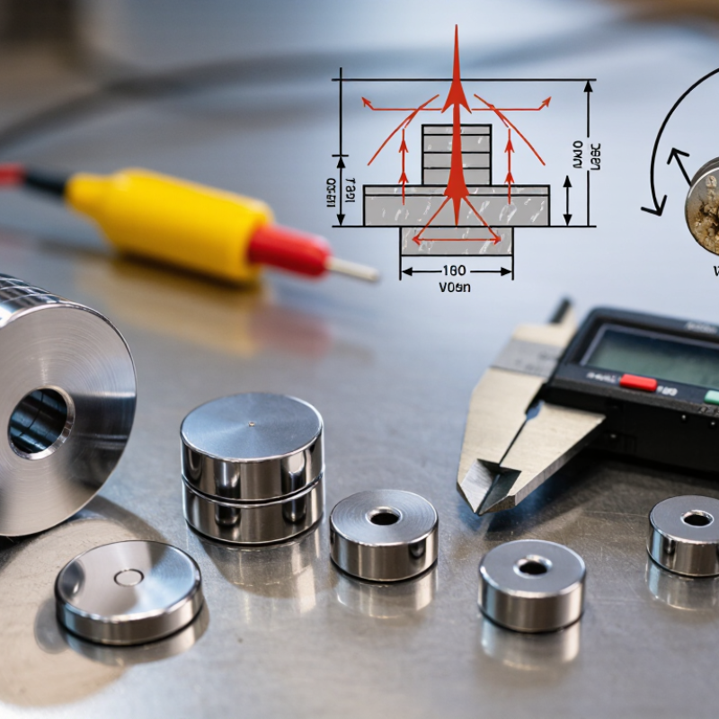
Define the Required Holding Force, Air Gap, and Safety Factor
Define the force at the real contact point, not from a catalogue’s best-case pull rating. That rating usually assumes thick, flat steel and direct contact. Paint, rust, a thin panel, or a small air gap can reduce holding force sharply. Measure the gap, including any coating, and test on the actual steel grade and thickness. Test in the direction of the load. Shear performance differs from straight pull.
A useful ideal estimate is F ≈ B²A/(2μ₀), where B is the working flux density and A is pole area. NIST’s CODATA value for μ₀ is about 1.256637 × 10⁻⁶ N/A². For example, 0.5 tesla across 10 cm² gives roughly 100 newtons under ideal conditions. Real assemblies may deliver less because flux is uneven and leakage occurs. IEC 60404-5 describes measurement methods for permanent-magnet properties; use measured assembly data, not material values alone, when sizing a magnet.
Then set a safety factor against the worst credible load. A factor of two or three may suit a stable, noncritical static load, but vibration, impact, temperature, and corrosion can demand more. Consider the failure consequence, too. A tidy calculation can still mislead. Pull-test a sample at the intended gap, with the real surface finish, and record the result. Use qualified engineering review where a dropped part could injure someone.
How to Choose the Right Neodymium Magnet - Define the Required Holding Force, Air Gap, and Safety Factor | Example Application | Maximum Working Load | Air Gap to Allow For | Suggested Safety Factor | Minimum Design Holding Force | Selection Check |
| Light cabinet or access panel | 20 N | 0 mm (direct contact) | 2 | 40 N | Verify the magnet’s pull force on the actual steel surface and panel thickness. |
| Positioning a small sensor on a coated steel surface | 10 N | 0.5 mm coating or spacer | 3 | 30 N at the specified gap | Use a force value tested at a 0.5 mm gap; a zero-gap rating is not an equivalent value. |
| Removable equipment cover | 50 N | 1 mm surface separation | 3 | 150 N at the specified gap | Check the complete magnet-to-steel assembly, including paint, adhesive, and any nonmagnetic layers. |
| Component mounted above people or equipment | 15 N | 0 mm (direct contact) | 5 | 75 N | Use a higher safety factor for consequences of release, and consider a mechanical backup restraint. |
| Outdoor gate or fixture with a nonmagnetic cover layer | 80 N | 2 mm cover or clearance | 4 | 320 N at the specified gap | Confirm holding force at the real gap and account for vibration, corrosion protection, and temperature. |
| How to use these examples: Minimum design holding force = maximum working load × safety factor. These are illustrative sizing scenarios, not universal magnet ratings or certified design values. Neodymium magnet pull force is usually specified for a direct, perpendicular pull against clean, thick, flat steel; air gaps, coatings, thin steel, surface roughness, temperature, and off-axis or sliding loads can reduce performance. For a reliable selection, use force data measured under conditions matching the actual installation and test the complete assembly. |
Compare N35–N52 Grades by Energy Product: About 33–52 MGOe
Neodymium magnet grades are compared by maximum energy product, or BHmax, measured in MGOe. Typical industry property tables, including data organized under MMPA Standard No. 0100-00, place N35 around 33–36 MGOe and N52 around 49–52 MGOe. That is a meaningful gap. For the same magnet volume, a higher BHmax can deliver more magnetic energy, or help designers use a smaller magnet. IEC 60404-8-1:2018 provides a framework for specifying permanent-magnet materials, but actual values and tolerances should be checked on the supplier’s technical datasheet.
The grade label is only part of the choice. A small disc marked N52 may not outperform a larger N35 block across a wide air gap; shape, thickness, and contact distance matter. Picture two magnets holding a steel plate: even a thin paper spacer can change the pull you feel. Easy to overlook. Check coercivity and maximum operating temperature too, especially near heat or external magnetic fields. N35 may be the sensible choice when cost, availability, or temperature stability matters more than peak energy product. N52 can suit tight spaces, but its higher number does not guarantee a stronger finished assembly. Test the actual geometry. It is an imperfect shortcut, but a useful one.
Match Temperature Ratings: N 80°C, H 120°C, SH 150°C, UH 180°C
The letter after an NdFeB grade signals its approximate maximum operating temperature: N is 80°C, H 120°C, SH 150°C, and UH 180°C. These are not guaranteed safe-use temperatures. The usable limit also depends on magnet shape, magnetic circuit, and the field resisting demagnetization. A small magnet in a narrow air gap may lose performance sooner than a larger magnet in the same heat. Check the supplier’s temperature curve, not just the grade label.
Temperature changes matter before the rated limit. Coey’s Magnetism and Magnetic Materials (2010) reports typical NdFeB temperature coefficients near −0.11% per °C for remanence and about −0.6% per °C for coercivity. In practical terms, a warm magnet can become easier to demagnetize, even when it still attracts a steel washer. Allow margin for hot spots, repeated heating, and poor airflow. Measure near the magnet, not across the room. An SH or UH grade may help, but it can have lower room-temperature magnetic output than an N grade. I would not select by temperature alone; the application’s actual field and heat cycle need checking.
How to Choose the Right Neodymium Magnet — Match Temperature Ratings: N 80°C, H 120°C, SH 150°C, UH 180°C
Compare the magnet’s maximum operating temperature with the highest temperature expected in your application. These are typical grade limits; actual performance can also depend on magnet shape, size, magnetic circuit, and operating conditions.
Choose Magnet Shape, Dimensions, and Magnetization Direction
Choose the shape by the load path, not appearance. A disc suits compact face-to-face contact, while a block offers a wider mounting surface. A ring can fit around a shaft, but its inner and outer edges need enough clearance. Measure the available space, including coating thickness and assembly gaps. Small gaps matter.
IEA’s Global Critical Minerals Outlook 2024 reports that China accounted for about 94% of global sintered permanent-magnet production in 2022. That concentration makes clear specifications and repeatable sourcing especially useful.
Dimensions control more than fit. A thicker magnet often delivers stronger attraction across a gap, but the result depends on the steel target, geometry, and grade. Don’t compare pull-force figures without checking how each was measured.
Magnetization direction matters just as much: common axial magnets have poles on their flat faces; diametrically magnetized cylinders have poles along opposite curved sides. Radial and custom patterns serve specific assemblies. This is easy to overlook.
Before ordering, sketch the magnet and mark its north and south faces, then confirm the direction with the supplier. I would still test a sample in the actual fixture; calculations can miss a bracket, coating, or awkward air gap.
Select Corrosion Protection: Ni-Cu-Ni, Epoxy, or Zinc Coating
A coating is the magnet’s first defense against moisture and handling damage. For many indoor applications, Ni-Cu-Ni plating is a practical general-purpose choice. Its familiar bright finish is compact and usually suits close-fitting assemblies. Still, plated layers can crack or wear if magnets collide. Small defects matter.
Epoxy coating is worth considering in humid settings or where extra corrosion resistance is needed. It forms a thicker barrier, but that thickness can affect tight clearances. The surface may also chip under impact or repeated rubbing. Check edges and mounting points, not just the flat face. A damaged coating can expose the magnet beneath it.
Zinc can provide basic protection at a lower cost, especially in relatively mild conditions. It is generally a weaker choice for persistent moisture or demanding exposure. Don’t choose by coating name alone. Ask for test data tied to the actual environment, including humidity, salt exposure, and temperature. A detail that is easy to overlook: cleaning chemicals and scratches can change how well any coating performs. Recheck the choice if the magnet will be washed often.