
What Is a Mechanical Shaft Seal and How Does It Work?

A Mechanical Shaft Seal keeps process fluid inside a pump or other rotating machine while limiting leakage along the shaft. It works through two carefully finished faces: one rotates with the shaft, while the other remains fixed. A thin fluid film separates them. Too much leakage is costly; too little lubrication can overheat and damage the faces. The details matter.

The market is substantial, though market size does not measure seal performance. Grand View Research estimated the global mechanical seals market at about US$4.62 billion in 2023 and projected growth through 2030. Robert K. Flitney, author of Seals and Sealing Handbook, is a respected reference in sealing engineering. A concise paraphrase—not a verbatim quotation—of his practical guidance is: “Seal reliability depends on matching the design, materials, and operating conditions.” That is easy to overlook.

In service, pressure, temperature, shaft movement, and fluid chemistry all affect the seal. Picture a pump running hot, with a faint leak tracing the shaft: the visible drip may be small, but the cause could involve installation, poor lubrication, or worn faces. A seal is not a universal plug. Selection requires operating data and careful inspection, and even experienced teams can miss early warning signs. This introduction explains the main components, the face-film principle, common seal arrangements, and the conditions that influence service life. It also leaves room for an important question: is the seal itself failing, or is the machine asking it to work beyond its design limits?
What Is a Mechanical Shaft Seal and How Does It Work?

What a Mechanical Shaft Seal Is: Rotating and Stationary Faces at the Shaft

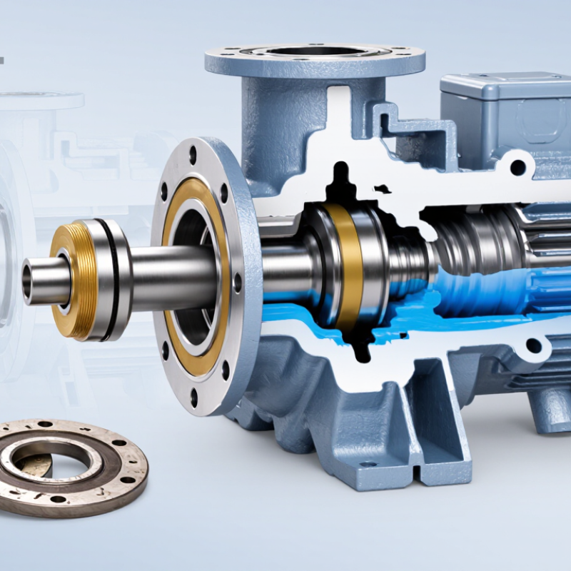
A mechanical shaft seal limits fluid leakage where a rotating shaft passes through a pump or other housing. Its main sealing interface consists of two closely matched faces. One face rotates with the shaft; the other remains stationary in the seal housing. The rotating face is often held by a sleeve and spring assembly, while the stationary face sits in a fixed seat.

The faces press together, but a thin film of process fluid usually separates them during operation. This film lubricates the contact and carries away heat. The gap is extremely small, so scratches, dirt, or uneven face pressure can change how the seal behaves. Some leakage may occur; a mechanical seal is not automatically a perfectly dry barrier. Small details matter.

Secondary seals, such as elastomer rings, close paths around the shaft and stationary seat. Springs help maintain face contact as parts move or wear, though their force must suit the operating conditions. A useful inspection habit is to check shaft runout, face condition, and cleanliness before installation. A seal can look sound and still fail early if the faces are misaligned. This is easy to overlook, and operating conditions can make the diagnosis less certain.

Core Parts: Seal Faces, Secondary Seals, Springs, and Gland

A mechanical shaft seal controls leakage where a rotating shaft passes through a pump casing. Its main barrier is the pair of seal faces. One face rotates with the shaft; the other stays fixed in the gland. Their polished surfaces run close together, with a thin liquid film helping reduce friction and heat. The faces should not be treated as perfectly dry or indestructible. Even a small scratch can affect sealing.

Secondary seals, often made from elastomeric materials, close gaps around the shaft and stationary components. They also allow slight movement as parts warm, cool, or shift. Springs provide force that keeps the faces in contact when pressure or movement changes. Some designs use a single spring; others distribute the load across several springs. Small parts, big consequences.

The gland supports the stationary face and holds the seal assembly against the equipment casing. It may also include passages for cooling or flushing, depending on the application. During installation, clean surfaces and correct alignment matter. A seal can look sound yet fail early if it runs dry or sits unevenly. This is easy to underestimate. Checking the equipment’s operating conditions and seal instructions is more reliable than assuming every arrangement works the same way.

How It Works: A Micrometre-Scale Fluid Film Lubricates the Seal Faces

A mechanical shaft seal limits leakage where a rotating shaft passes through a stationary pump casing. Its two lapped faces meet under spring and hydraulic forces. Yet they do not normally run completely dry. A thin process-fluid film separates them, reducing friction and carrying away heat. It is remarkably small. Industry seal-design references, including the Fluid Sealing Association’s Mechanical Seal Handbook, describe face films commonly measured in micrometres; actual thickness varies with fluid, pressure, speed, and face geometry. Published engineering guidance often places the working film around 0.5–3 μm, but this is not a universal setting.

As the shaft turns, viscous drag draws fluid into the narrow interface. Microscopic surface features and slight face distortion help sustain the film while keeping leakage low. API Standard 682 provides qualification and operating guidance for process-pump sealing systems, though it does not make one film thickness suitable for every duty. In field checks, temperature trends, leakage, vibration, and flush conditions can reveal trouble before a face visibly fails. A cloudy flush line or sudden temperature rise deserves attention. Small changes matter. The simple model can mislead: real fluids contain particles, and startup briefly disrupts lubrication. That is why seal selection and operating records matter as much as the nominal clearance.

What Is a Mechanical Shaft Seal and How Does It Work? — How It Works: A Micrometre-Scale Fluid Film Lubricates the Seal Faces
Dimension Typical Description or Value How It Affects Seal Operation
Primary sealing faces Two closely fitted, flat annular faces: one rotates with the shaft and the other is held stationary. The faces restrict fluid escaping along the shaft while allowing rotation with very little contact.
Lubricating film thickness Typically on the order of a few micrometres; the exact thickness varies with seal design and operating conditions. A thin process-fluid film separates and lubricates the faces. It also carries away heat generated at the interface.
Film composition Usually the sealed liquid itself; in some services, the film may include a small amount of vapor. The fluid’s viscosity, vapor pressure, temperature, and cleanliness influence film stability and leakage behavior.
Face loading A spring and fluid pressure apply closing force; hydraulic forces in the seal balance help determine the net load. The closing force maintains face proximity, while the fluid film prevents excessive solid-to-solid contact during normal operation.
Surface finish Seal faces are precision lapped to a very smooth finish; the specified finish depends on materials and design. Flat, smooth faces help maintain a stable film and reduce localized wear and leakage paths.
Leakage path Fluid can pass through the microscopic interface between the faces. Some leakage is inherent in a lubricated face seal. Depending on conditions, it may be extremely small and may evaporate near the seal exterior.
Heat management Heat is produced by fluid shear and any face contact, especially during start-up or poor lubrication. Circulation of the liquid film and, where provided, a seal flush or cooling arrangement help control face temperature.
Start-up and dry running The lubricating film may not be fully established before the equipment reaches operating conditions. Running without suitable liquid at the faces can cause rapid heating, wear, or face damage. Start-up procedures depend on the equipment and seal arrangement.
Performance influences Pressure, shaft speed, temperature, fluid properties, alignment, vibration, and contamination all matter. These conditions affect film formation, face loading, leakage, and service life; values should be checked against the specific seal design.
Typical materials Face pairs commonly use combinations such as carbon graphite against silicon carbide or tungsten carbide. Material selection balances wear resistance, chemical compatibility, thermal behavior, and the properties of the sealed fluid.

API 682 Seal Arrangements: 3 Configurations for Single and Dual Seals

What Is a Mechanical Shaft Seal and How Does It Work?

API 682 Seal Arrangements: 3 Configurations for Single and Dual Seals

A mechanical shaft seal limits fluid leakage where a rotating shaft passes through a pump casing. Its faces run close together, with a thin fluid film helping reduce friction and wear. API 682 describes three common seal arrangements for selecting equipment around the process fluid and operating conditions. Arrangement 1 uses one seal. It is often considered when leakage control needs are moderate and the pumped fluid is manageable. Arrangement 2 uses two seals with an unpressurized buffer fluid between them. Leakage from the inner seal can enter this buffer system, so monitoring matters. Arrangement 3 also uses two seals, but its barrier fluid is maintained above the pressure of the sealed fluid. This helps prevent process fluid from escaping through the inner seal.

The right arrangement depends on more than fluid pressure. Temperature, volatility, solids, startup conditions, and the consequences of leakage all matter. Arrangement 2 is not simply a cheaper Arrangement 3; their fluid systems serve different purposes. A tidy piping diagram can still miss practical issues, such as poor venting or inadequate circulation. Those details deserve a second look during design reviews.

Tips: Confirm buffer or barrier fluid compatibility and pressure requirements before specifying a seal. Check the applicable API 682 edition and consult a qualified seal specialist for demanding service. Keep operating limits visible for maintenance teams. Small oversights matter.

How to Select a Seal: Pressure, Speed, Fluid, and Operating Conditions

A mechanical shaft seal controls leakage where a rotating shaft enters a pump or mixer housing. Two faces press together, with a thin fluid film between them. This film reduces friction. Dry running can quickly overheat the faces and damage elastomers. Select a seal using actual operating data, not just the equipment nameplate.

Pressure and shaft speed affect seal load and heat. Check normal pressure, startup pressure, and occasional peaks, then compare shaft speed with the seal’s rated limits. Fluid matters just as much. Viscosity, abrasive particles, crystals, and chemical compatibility can change face wear or swell secondary seals. Temperature and frequent starts count, too. A seal suited to clean water may fail early in hot, gritty fluid. Operating conditions can change, and field records are not always complete. Verify assumptions before ordering.

Tips: Record fluid composition, temperature range, pressure, speed, and whether solids are present. Ask a qualified seal specialist to review unusual operating conditions. Leave room for uncertainty. A short test run may reveal heat or leakage that calculations miss, but it cannot replace specified limits or correct installation. Small details matter. Proper alignment and clean seal faces help prevent premature wear.

CONTACT US