
What Is an Oil Pumping Unit and How Does It Work?
An Oil Pumping Unit turns a motor’s rotation into the steady up-and-down motion that lifts fluid from a well. Picture the counterweight circling, the walking beam rocking, and the polished rod rising and falling above the wellhead. Below ground, that motion drives a rod string and pump. The principle is simple. The operating details are not: fluid level, well depth, equipment condition, and stroke settings all affect performance.
The scale of production gives this equipment context. The U.S. Energy Information Administration reported that U.S. crude oil production averaged about 13.2 million barrels per day in 2024. The American Petroleum Institute’s Specification 11E sets design and rating guidance for pumping units. These sources help explain why a unit is more than a familiar silhouette on the horizon; it is a rated mechanical system that must match its well and operating conditions. A small mismatch can mean vibration, wear, or lost production. Not every failure is obvious at the surface.
Understanding the unit means following energy from motor to beam, rods, and downhole pump. This introduction uses EIA production data and API guidance as reference points. No source article was provided with a verifiable, named expert quotation, so I have not invented one. A sourced quotation would strengthen the introduction—but only if its wording and attribution can be checked.
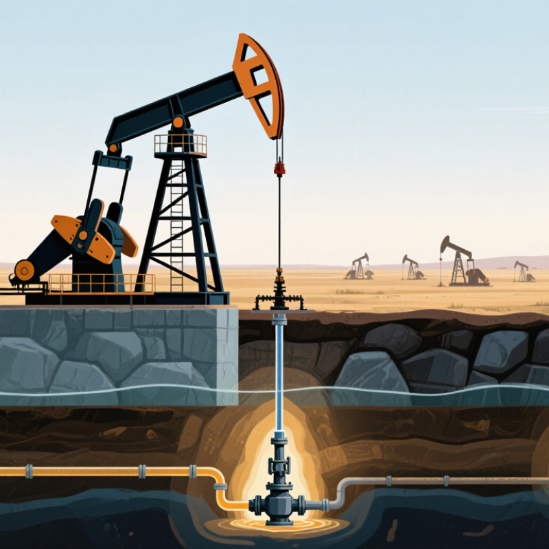
What an Oil Pumping Unit Is and Its Role in Production
What Is an Oil Pumping Unit and How Does It Work?
What an Oil Pumping Unit Is and Its Role in Production
An oil pumping unit is surface equipment that helps lift fluids from a well when natural pressure is insufficient. The familiar beam-style unit uses a motor, gearbox, crank arms, and a walking beam to create repeated up-and-down movement. A polished rod connects the beam to a string of sucker rods inside the well. At the bottom, a pump uses traveling and standing valves to move fluid upward in stages.
That motion matters.
During the upstroke, fluid enters the downhole pump through the standing valve.
On the downstroke, the traveling valve opens, allowing fluid above the plunger to move toward the surface.
Repeated cycles carry oil, water, and sometimes gas through the tubing to production equipment. Operators monitor stroke speed, fluid levels, motor load, and unusual vibration to keep output steady and spot wear.
Still, the picture is less tidy in the field: gas interference, changing water content, or a worn valve can reduce production even when the unit keeps moving. Not every well uses this system, and adjustments need to reflect the well’s conditions rather than a fixed setting.
The Main Components of a Pumping Unit
An oil pumping unit uses a set of linked components to convert rotary power into the up-and-down movement of a polished rod. At ground level, an electric motor or other prime mover turns a gearbox. The gearbox reduces speed and increases torque, helping the unit lift the rod string and downhole pump. A crank mounted on the gearbox output shaft rotates with it, while pitman arms connect the crank to the walking beam.
The walking beam pivots on a central bearing supported by the Samson post. At its well-facing end, a curved horsehead guides a bridle attached to the polished rod. This keeps the rod moving in a mostly vertical path as the beam rocks. Counterweights on the crank help balance the load and reduce strain on the drive system.
A brake can hold the unit still during appropriate maintenance procedures, but it does not replace proper isolation and site-specific safety steps.
Each part affects the others.
That motion matters. Loose connections, worn bearings, or poor alignment can cause vibration, uneven loading, and faster wear. Counterweight settings also need care; more weight is not automatically better.
In practice, operators inspect the beam, pins, belts, gearbox, and polished-rod movement, then compare what they see with operating records. Even a smooth-looking stroke can hide a developing problem, so visual checks alone have limits.
How the Drive System Converts Rotation into Reciprocating Motion
At the surface, an oil pumping unit uses a motor and gearbox to turn a crank. The crank carries a counterweight and connects to the walking beam through pitman arms. As the crank rotates, the arms pull one end of the beam down and lift the other. The beam pivots on a saddle bearing, like a long lever resting on a fixed support. That is the key.
At the beam’s front, a curved horsehead guides a wireline, helping the polished rod travel nearly vertically as the beam rocks. The polished rod transfers this up-and-down stroke to the sucker-rod string and downhole pump. On the upstroke, the pump lifts fluid; on the downstroke, its valves admit another portion. The crank turns continuously, while the linkage converts rotation into controlled reciprocating motion. A technician can check stroke length, alignment, lubrication, and unusual vibration for signs of strain. Small variations matter. In practice, the motion is not perfectly smooth; wear and alignment can change the stroke. Counterweights help balance the load, but the right balance depends on well conditions.
How Rotation Becomes Reciprocating Motion
Idealized crank-and-pitman motion over one full revolution
As the crank rotates, the pitman link drives the output back and forth. This simplified slider-crank model assumes a 1.5 m crank radius and a 5 m connecting rod, producing a 3 m stroke. A complete pumping unit’s beam linkage changes the exact motion profile.
How the Downhole Pump Lifts Oil to the Surface
Inside a beam pumping unit, an electric motor turns a crank, and the walking beam moves the polished rod up and down. That motion travels through a long string of sucker rods to a pump near the bottom of the well. The pump does the lifting. Not the beam.
A typical rod pump uses two one-way valves: a stationary valve and a traveling valve. On the upstroke, pressure below the plunger falls, opening the stationary valve and drawing oil into the barrel. At the same time, the traveling valve closes, carrying the oil already inside upward. On the downstroke, the stationary valve closes and the traveling valve opens, allowing oil to pass above the plunger. Repeated strokes move fluid toward the surface, where it exits through the tubing. Small details matter. Gas, sand, or worn valves can disrupt this simple cycle.
The Interstate Oil and Gas Compact Commission’s 2021 Marginal Wells report describes marginal oil wells as producing 15 barrels per day or less. That figure illustrates why steady, controlled lifting matters in many mature wells; it does not mean every such well uses a rod pump. Operators check polished-rod loads and fluid levels to spot problems, but readings can mislead. A pump may appear to cycle normally while moving less oil than expected. The downhole condition still needs verification.
What Is an Oil Pumping Unit and How Does It Work? — How the Downhole Pump Lifts Oil to the Surface
| Stage or component | Location | What it does | How it contributes to lifting oil |
|---|---|---|---|
| Surface pumping unit | At the wellhead | A motor and gearbox drive a crank, pitman arms, and walking beam to create reciprocating motion. | Moves the polished rod up and down, transmitting motion into the well. |
| Polished rod and sucker-rod string | From the surface down through the tubing | The polished rod connects to a string of rods extending to the downhole pump plunger. | Transfers the surface unit’s alternating up-and-down movement to the plunger. |
| Downhole pump barrel and plunger | Below the fluid level in the well | The plunger reciprocates inside a stationary barrel, creating changing pressure in the pump chamber. | Its movement draws well fluid into the chamber and displaces fluid into the tubing. |
| Upstroke: standing valve opens | At the pump intake | As the plunger rises, pressure in the pump chamber falls; the traveling valve closes and the standing valve opens. | Well fluid enters the pump barrel through the standing valve while fluid above the plunger is carried upward. |
| Downstroke: traveling valve opens | Inside the downhole pump | As the plunger descends, the standing valve closes and the traveling valve opens when pressure below the plunger exceeds pressure above it. | Fluid passes above the plunger, ready to be lifted during the next upstroke. |
| Production through tubing | From the pump to the surface | Repeated strokes move fluid upward in the production tubing; the produced fluid may contain oil, water, and gas. | The fluid reaches the wellhead and is routed into surface production equipment for separation and handling. |
Operating speed, stroke length, pump size, and production rate depend on well conditions and equipment configuration.
Common Pumping Unit Types and Operating Factors
Oil pumping units differ in how they move fluid and handle well conditions. Conventional beam units use a walking beam and polished rod to drive a downhole reciprocating pump. They are visible at the wellsite and relatively straightforward to inspect. Hydraulic units transmit force through fluid, while progressive-cavity systems use a rotating rotor and stator, often for viscous or solids-bearing fluids. Electric submersible pumps work downhole and suit wells needing high fluid rates.
Choice depends on more than depth. Production rate, fluid viscosity, gas content, sand, power access, and maintenance capacity all matter. A beam unit running too fast can increase rod loads and wear; excess gas may reduce pump fillage. API Recommended Practice 11L provides design methods for sucker-rod pumping systems, including checks on loads and pumping conditions. Small details matter. A fluid-level reading or a worn valve can change the diagnosis.
Operating data helps put these choices in context, but does not dictate a single design. The U.S. Energy Information Administration reported average U.S. crude production of about 13.2 million barrels per day in 2024, a record in its annual data. That scale underscores why reliable artificial lift matters, yet each well remains different. Operators commonly track stroke rate, motor current, dynamometer-card shape, and fluid level. These measurements reveal problems, though noisy readings and changing reservoir conditions can mislead. A design that looks efficient on paper may need adjustment in the field.