
Why Is Die Casting Mold Design Important?

A Die Casting Mold may look like a steel block with polished cavities, but its design governs how molten metal fills, cools, and releases. A small mistake in gate placement can leave a thin section short of metal. Poor venting may trap air, while uneven cooling can distort a part or shorten tool life. These are not abstract risks; they show up on real production lines as scrap, rework, and downtime.

The market’s scale makes careful design matter. Grand View Research estimated the global die casting market at USD 73.5 billion in 2023 and projected a 6.4% compound annual growth rate from 2024 to 2030. Market growth alone does not prove that every project needs a complex mold. It does show why manufacturers scrutinize tooling decisions, from alloy selection to cooling-channel layout. The report measures market value, not mold performance, so those figures should be read in context.

Casting researcher and author John Campbell is a recognized authority on casting processes. A practical design maxim aligned with his work is: “A mold must control metal flow, heat, and solidification as one system.” That is a guiding principle, not a substitute for simulation or shop-floor testing. Real parts can still surprise you. A sound Die Casting Mold design connects product geometry with process conditions, inspection needs, and maintenance plans—and it leaves room to question assumptions before steel is cut.
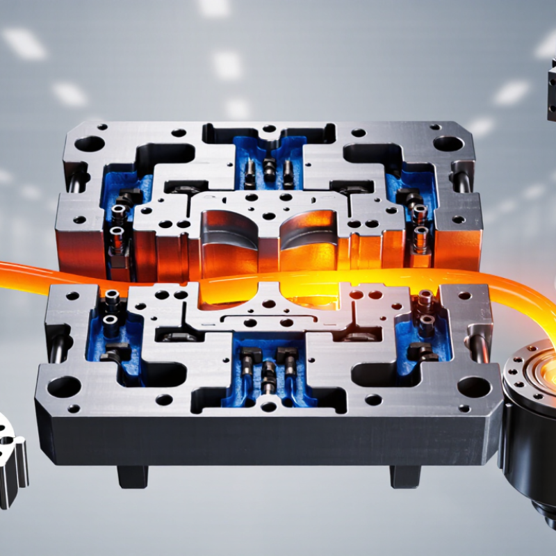
Why Is Die Casting Mold Design Important?

What Mold Design Controls in High-Pressure Die Casting at 70–100 MPa

Why Is Die Casting Mold Design Important?

What Mold Design Controls in High-Pressure Die Casting at 70–100 MPa

At 70–100 MPa, the machine drives molten metal into a closed steel die with substantial force. The exact pressure depends on the machine and process. Mold design helps control where the metal flows, how quickly the cavity fills, and where air escapes. A poorly placed gate can leave a cold seam or trap gas near a thin rib. Those defects may appear only after trimming or machining.

Vents and overflow wells give displaced air and early, cooler metal a path out. Cooling channels influence how evenly the die sheds heat, while the parting line and locking surfaces help resist separation and reduce flash. Small details matter. Even a slight change in wall thickness can alter filling and cooling, so trial results should guide adjustments rather than guesswork. Design cannot eliminate every defect, but it can make the process more predictable.

Tips: Review fill patterns, vent locations, and likely hot spots before cutting the die. Check sample parts for porosity, flash, and uneven dimensions. Keep a record of each adjustment; one improvement can expose another weak point. That is worth reviewing.

How Gate, Runner, and Vent Layout Guide Metal Filling and Air Escape

Die-casting mold design matters because metal needs a clear route into the cavity and trapped air needs a way out. The gate sets the entry point, direction, and speed of the melt. A gate that is too small may restrict flow and cool the metal early. One placed poorly can send metal across a thin rib, leaving a weak or incomplete area.

The runner carries metal from the sprue to the gates. Its branches should distribute flow evenly, rather than filling one section much earlier than another.

Vents give displaced air and gases an escape path near the last areas to fill. If vents are shallow, blocked, or poorly located, air pockets may remain and cause porosity. Small details matter. A layout can look balanced on screen and still behave differently during a real shot; simulation helps, but it does not replace careful trials and inspection.

Tips: Check the expected fill sequence, especially around thin walls and sharp corners. Keep vents near likely air traps, and make them practical to clean. Record casting results; the first adjustment is not always the right one.

Why Wall Thickness Matters: Aluminum Castings Commonly Use 1.5–4 mm Walls

Aluminum die castings commonly use walls around 1.5–4 mm, but that range is a guide, not a guarantee. Reliable filling also depends on alloy, part size, flow distance, gate placement, and die temperature. A long, thin channel may freeze before metal reaches its far end, leaving incomplete edges or weak areas. Thicker sections stay hot longer and can increase cooling time or promote shrinkage near junctions. Small changes matter.

Keeping walls reasonably even helps metal flow and cool more predictably. Where thickness must change, gradual transitions and rounded corners can reduce abrupt hot spots. Ribs can add stiffness without making an entire panel thicker, but oversized ribs may create their own cooling problems. A 2 mm wall might work well in one component and prove difficult in another; geometry matters. Flow simulation can help identify slow-filling regions, yet its results depend on accurate process inputs. A production trial may still reveal a thin corner that cools sooner than expected.

How Cooling and Ejection Design Influence Cycle Time and Part Quality

Why Is Die Casting Mold Design Important?

Cooling and ejection design directly affect how quickly a die can cycle and how consistently it produces usable parts. Cooling channels should remove heat evenly, especially around thick sections, ribs, and areas near the gate. A hotspot can delay ejection or leave a part prone to sink marks and dimensional variation. Small details matter.

Channel placement is a trade-off. Channels too far from the cavity may cool slowly, while channels too close can weaken the mold or create uneven temperatures. A tidy layout on a drawing does not guarantee good cooling in production. Measurements from trial runs can reveal hot spots that simulation missed, so designers should be ready to revise the plan.

Ejector pins also influence both cycle time and surface quality. Their positions should support the casting without leaving visible marks on important surfaces. If ejection starts while the part is too hot, thin walls may bend or pins may leave deeper impressions. If the casting sticks, operators may need to pause the cycle and remove it carefully. That costs time. Reviewing pin marks, part distortion, and release behavior after each trial helps refine the design; even a well-considered first layout may need adjustment.

Why Is Die Casting Mold Design Important? — How Cooling and Ejection Design Influence Cycle Time and Part Quality

Design Dimension Design Consideration Potential Effect on Cycle Time Potential Effect on Part Quality Useful Checks or Measurements
Cooling-channel layout Place channels to remove heat from thick sections and other hot spots while maintaining appropriate distance from the cavity surface. More effective, balanced heat removal can reduce the time needed for the casting to reach a safe ejection temperature. More even cooling can reduce temperature gradients that contribute to distortion, residual stress, and inconsistent solidification. Cooling-water flow and temperature; mold-surface temperature map; time to reach the ejection-temperature target.
Cooling balance between mold halves Coordinate cooling on the moving and fixed halves rather than treating each side independently. Balanced heat extraction can help avoid extending the cycle to compensate for one persistently hot area. Can reduce uneven shrinkage and help maintain dimensional consistency across the casting. Temperature difference between corresponding mold areas; dimensional variation across repeated parts.
Local hot-spot control Identify heavy sections, intersections, and areas around cores where heat may accumulate; use suitable local cooling or thermal-management features. Addressing a slow-cooling region may prevent it from setting the minimum cycle time for the whole part. Can help limit localized defects associated with uneven solidification, subject to alloy, geometry, and process conditions. Thermal simulation results; observed hot spots; defect location and frequency during process trials.
Cooling-channel condition Design for practical cleaning, inspection, and reliable coolant flow; account for scale, blockage, and leakage risks. Maintained flow helps keep cooling performance consistent and reduces interruptions for troubleshooting. Stable thermal conditions support repeatable dimensions and surface results from shot to shot. Flow rate, inlet and outlet temperatures, pressure drop, leakage checks, and maintenance records.
Ejector-pin placement Locate pins on robust areas that can withstand ejection force, and distribute them to support the casting without interfering with critical surfaces. Reliable release can reduce sticking-related pauses and the need for manual intervention. Balanced support helps reduce ejector marks, local deformation, cracking, and bending during ejection. Pin-mark location and depth; ejection-force trends; part distortion after ejection.
Ejection balance and timing Use a coordinated ejection system and eject only after the casting has sufficient strength to withstand the applied forces. Consistent release can make the ejection stage more predictable; ejecting too early may cause handling delays or rejects. Appropriate timing and balanced force help prevent deformation, cracks, and damage to thin or unsupported features. Ejection timing; force or pressure trends; scrap and rework associated with ejection damage.
Draft and release geometry Provide suitable draft and avoid unnecessary undercuts or surface features that resist separation from the die. Easier release can shorten or stabilize the opening and ejection portion of the cycle. Reduces the risk of drag marks, surface tearing, and damage during removal. Release consistency; drag marks; dimensional and surface inspection after ejection.
Integrated cooling and ejection design Check that cooling channels, cores, ejector pins, and other mold components fit together and remain accessible for service. Early coordination can avoid design changes, maintenance delays, and cycle instability caused by conflicting features. Supports repeatable thermal behavior and controlled part release across production runs. Tooling design reviews; simulation and trial results; cycle-time variation; maintenance access.

Note: Effects are directional, not guaranteed numerical outcomes. Actual cycle time and part quality depend on the alloy, casting geometry, machine settings, mold condition, and production process; confirm design decisions through engineering analysis and production trials.

How Tooling Design Supports Die Life, Often Ranging from 100,000 to 1,000,000 Shots

Die casting tooling may run from roughly 100,000 to 1,000,000 shots, but that range is not a guarantee. Actual die life depends on alloy, part geometry, machine settings, maintenance, and thermal cycling. Each injection heats the cavity; cooling then pulls heat away. Repeated expansion and contraction can cause heat checking, especially near thin cores and sharp corners. Small details matter.

A robust design manages those stresses before the first pour. Uniform wall sections, generous radii, and well-placed cooling channels help reduce hot spots. Gates and runners should fill the cavity consistently, while vents allow trapped air to escape. Ejector pins need support and sensible placement, or they may mark parts and wear surrounding steel. These choices are best checked against the casting’s real geometry and production conditions, not just a clean-looking model. On the shop floor, a channel that seems ideal on screen can be hard to clean or maintain. That is worth reconsidering.

Tool steel selection, heat treatment, and accessible maintenance features also influence service life. A mold designed for inspection makes it easier to catch cracking, erosion, or buildup early. Shot counts should be tracked alongside repair history and part quality. Two similar dies can age differently. The difference is often in details that were easy to overlook.

CONTACT US